MCS-I32
MultiClick Multi Circuit Monitoring
Current Transformer Input Module
- Product videos
Multi-Click demonstration video
- Product variants
- MCS-I30 - Total, Nett, Import, Export kWh/kVArh, L1,L2,L3 Amps, Power (Active / Reactive / Apaprent) and Power Factor.
- MCS-I31 - Total, Nett, Import, Export kWh/kVArh, L1,L2,L3 Amps, Power (Active / Reactive / Apaprent), Power Factor and THD
- MCS-I32 - Total, Nett, Import, Export kWh/kVArh, L1,L2,L3 Amps, Power (Active / Reactive / Apaprent), Power Factor, THD, Max Demand and Overload Alarm Function
- Features
- 1 Module DIN rail mounted
- No voltage reference required (Voltage reference is taken from the MCS-U module for entire system)
- 3 x RJ12 CT inputs (3 x Single phase or 1 x Three phase sensor)
- RJ45 input and output for the interconnecting on the bus network
- Up to 32 x MCS-I modules on one network
- Entire network of MCS-I modules measured and displayed from one centralised point
- Product information
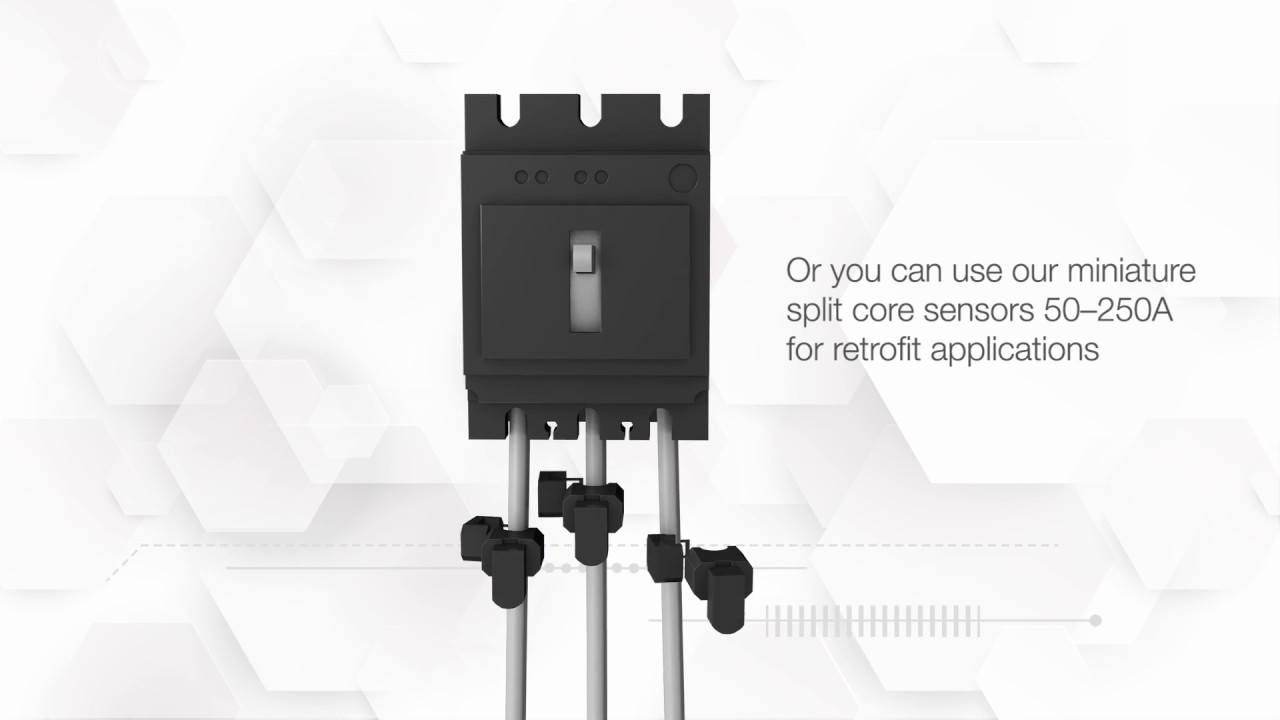
This new concept of intelligent measuring and monitoring of power management and distribution has been designed and engineered for new and retro fit applications. Up to 32 x Three Phase or 96 x Single Phase circuits measured and accessible from one centralized data display. The current, Power and Energy is monitored by the MCS-I module, which has three RJ12 inputs for three individual split core sensors or alliteratively you can just the first RJ12 input, if using our three-phase block sensor. There are three different levels of the MCS-I modules ranging from basic measurement to THD (Total Harmonic Distortion), power per phase and overload alarm functions. The MCS-I modules can then be interconnected via the RJ45 input/ output back to the Voltage and communication module (MCS-U) You can have up to 32 x MCS-I modules connected on one bus (32 x three phase or 96 x single phase circuits). There is no voltage reference required for the MCS-I module.
The MCS-U module is the Voltage and Communication module, you will connect your voltage reference for the complete system to this device (1ph2W or 3ph4W). It will be interconnected to the MCS-I module and the display Module (MCS-D) via RJ45 input / output ports. In the event you do not require a display, you can utilize the RS485 output on this module to program or to connect into a BMS system or energy management platform (Connex). Depending on the level of requirements we can provide a basic 96x96mm display which will measure the multiple circuits, it can also be used for the setting up of the entire system. Alternatively, we can offer a HMI screen which in conjunction with our Eastron ConneX, which can be used as a centralised metering data point or as a sub metering remote monitoring and data logging end to end solution.